| .::YAMAHA::. | ||||||||||||
| R D |
|
YAMAHA RD 350
ALL YOU WANT TO KNOW.....! |
||||||||||
|
3 5 0 |
The Expansion Chamber Designing ( TRY YOU OWN )
Description:
The expansion chamber design software is used to design the tuned pipe for
the exhaust system of the micro car engine. One can choose to design a single
stage, two-stage or a three-stage diffuser chamber according to their
requirements. This section details the various parameters and design formulae,
which have been implemented in the software design project. Sections of a Tuned Pipe:
Header - Attaches to the engine and is the straight or slightly
divergent (opens up 2-3 degrees) section of the pipe. It helps to suck the
exhaust gases out of the engine. The header pipe cross-sectional area should be
10-15% greater than the exhaust port window for when maximum output at maximum
RPM's is desired. In some cases the area of the header pipe may have a
cross-sectional area 150% of the exhaust port area. The length should be 6-8 of
its diameters for maximum horsepower, for a broader power curve 11 times pipe
diameter may be used. The part you trim off to tune. Divergent (Diffuser) Cone - The section of the pipe
that attaches to the header and opens up at an angle like a megaphone.
It intensifies and lengthens the returning sound waves thus broadening the
power curve. The steeper the angle the more intense the negative wave returns,
but also the shorter the duration. The lesser the angle, of course, returns a
less intense wave, but for a longer period of time (duration). The outlet area
should be 6.25 times the inlet area. 7-10 degree taper angle.
Belly - Located between the divergent and convergent cones, it's length determines the relative timing of the negative
and positive waves. The shorter the belly the shorter the distance positive
waves travel and the narrower the RPM range. This is good for operating at HIGH
RPM only. The longer the belly the broader the RPM range. The diameter of the
belly has little or no effect. Convergent (Baffle) Cone - Located after the belly and before the
stinger, reflects the positive waves back to the open exhaust port and forces
the fresh fuel mixture back into the combustion chamber as the exhaust port
closes. The steeper the angle the more intense the positive
wave and the gentler the angle the less intense. 14-20
degree taper angle. The taper angle primarily influences the shape of
the power curve past the point at which maximum power is obtained. Stinger - Located at the opposite end of the pipe from the header and
after the convergent cone, it is the "pressure relief valve" of the
pipe where the exhaust gasses eventually leave the pipe. The back pressure in
the pipe is caused by the size (diameter) or length of the stinger. A smaller
stinger causes more back pressure and thus a denser medium for the sound waves
to travel in. Sound waves love denser mediums and thus travel better. A draw
back to a small stinger is heat build up in the pipe and engine. The stinger
diameter should be 0.58--0.62 times that of the header pipe and a length equal
to 12 of it's own diameters. When the engine fires it detonates the fuel mixture in the combustion
chamber, pushes the piston down, opens the exhaust port and allows the burnt
gases to escape along with the sound wave produced when the engine fired. The
negative sound waves pull the exhaust gasses out of the exhaust port. The
positive sound waves, reflected back from the convergent (baffle) cone, force
the fresh fuel mixture back into the combustion chamber through the exhaust
port thus super-charging your engine. Common Engine Parameters to be calculated:
BMEP = Average Exhaust Temperature based on BMEP
Speed of Sound A0 = Where g is specific heat ratio of air i.e. 1.4 R is the Gas Constant of air i.e. 287 Texc is exhaust gas temperature The values for k1 and k 2 are ranges depending on the
type of engine. k1 ranges from 1.05 to
1.125 while k 2 ranges from 2.125 to 3.25. Finally the tuned length Lt = Where q
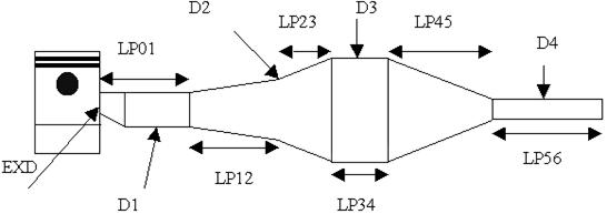
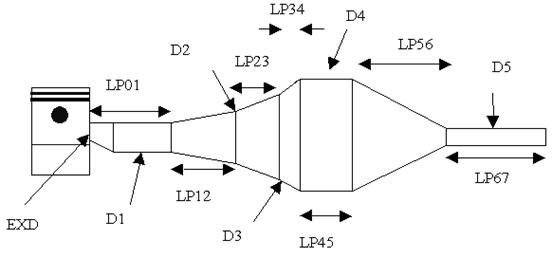
ep is exhaust port open duration in degrees Single Stage Diffuser Expansion Chamber Design:
Design Formulae: Lt = Where Lt is tuned length Eo is exhaust-open period Vs is sonic wave speed N is crankshaft speed L1 = L2 = L3 = L4 = L5 = L1 - (L3 + L4) L6 = L7 = D3 x 12 D1 is 10 to 15% greater than exhaust port window D2 = D3 = D1 x (0.58 to 0.62) A1 = (half the diffuser's angle of divergence) A2 = (half the baffle-cone's angle of divergence) |
|||||||||||
|
|
||||||||||||
|
|
||||||||||||
|
|
||||||||||||
|
|
||||||||||||
|
|
||||||||||||
|
|
||||||||||||
|
|
||||||||||||
|
|
||||||||||||
|
Website
designed & maintain by WEB-ARCH |
||||||||||||